Page 1 of 3
Re: Use GPIO pins to trigger scenes
Posted: Wed Jun 03, 2015 6:37 am
by karrika
I already have another project going on that uses MCP23S17 chips to extend SPI to bidirectional 16-bit I/O. It also supports interrupt capability. With one chip select I can add 8 chips. It means 128 I/O pins.
The Raspberry Pi has two SPI interfaces and several CE lines so there is really no restrictions of how many buttons you can use.
I had my first Raspberry Pi 2 show yesterday using unisolated switches to control everything. During the summer the plan is to build a pcb with isolated hardware. Would any of you be interested to join forces and participate in an open platform?
The board could have:
- a SPI MCP23S17 chip providing 16 isolated inputs
- 8 small pushbuttons
- 4 small rotary encoders
- dip-switches to set the SPI address. 3 bits set the logical address and 2 bits choose the CE/ signal allowing you to connect up to 16 boards (128 buttons and 64 rotary encoders)
- form factor 5cm by 10cm
- two 16-pin terminal blocks for external connections
This still leaves the second SPI bus for LED control.
Re: Use GPIO pins to trigger scenes
Posted: Wed Jun 03, 2015 9:11 am
by boxy
We use SPI for:
System ASICs (PSUs, I/O, diagnostics etc.),
G-sensors (accelerometers) and yaw-rate sensors,
EEPROM,
Coil drivers,
Electric Park Brake micro,
Comms diagnostics.
I'm more hardware than software, but I know SPI can be difficult to get running unless there are ready made routines out there you just blast data to.
Some ideas for connecting GIO are in the second link:
http://www.mosaic-industries.com/embedd ... ifications
http://elinux.org/RPi_GPIO_Interface_Circuits
One thing missing from the circuits are capacitors to filter ESD (Electrostatic Discharge). Typically these are 10nF, 50V parts on each pin going to the outside world. A second component to GND across each GIO pin will greatly stop risk of blowing the Pi up.
Re: Use GPIO pins to trigger scenes
Posted: Mon Jun 08, 2015 3:54 am
by iamchrislaurie
@karrika - I would certainly be interested in such a board. In my case I would like to fit joystick controls (x y return spring potentiometers) as opposed to rotary encoders. In other words analog data. So if the board could be had without the actual switches and knobs, that would be first prize. Maybe 2 boards rather?
The point of the joystick is the interaction with the level monitoring and relative settings in the input plugin. This allows my scene to set the value and the moving the joystick adjust the value from where it is currently and not the absolute value.
Being able to combine the 2 methods would also allow for more adaptability and versatility for us almost maker types.
Re: Use GPIO pins to trigger scenes
Posted: Mon Jun 08, 2015 8:57 am
by boxy
This sounds interesting, if it hasn't already been done?
I have access to Mentor Graphics software so we could get something going (schematics for a start).
Re: Use GPIO pins to trigger scenes
Posted: Tue Jun 09, 2015 8:50 am
by karrika
Thanks for the comments. While walking out with my daughters dog during the weekend I had some spare time to think about this. So far I can think of many different boards.
All boards would have a 40 pin plat cable input and output.
Board 1)
DMX board using pins 8 TXD, 10 RXD
Board 2)
Extended SPI board with lots of input pins
24 (SPI0 CE0), 26 (SPIO CE1), 19 (SPI0 MOSI), 21 (SPI0 MISO), 23 (SPI0 SCLK),
12 (SPI1 CE0), 11 (SPI1 CE1), 38 (SPI1 MOSI), 35 (SPI1 MISO), 40 (SPI1 SCLK)
The system provides 4 different SPI chip addresses. With dip switches or jumpers you can choose SPI0/SPi1 and CE0/CE1.
Once the address is known you can map 8 MCP23S17 chips to listen to this address.
One board would have one MCP23S17 chip, 16 isolated inputs through 4 RJ45 sockets, 1 isolated DC-DC power to feed the input switches.
Board 3)
Plain GPIO input pins.
3, 5, 7, 13, 15, 16, 18, 22, 27, 28, 29, 31, 32, 33, 37
15 isolated inputs through 4 RJ45 sockets, 1 isolated DC-DC power to feed the input switches.
Board 4)
Extended SPI board for analog inputs. Joysticks, sliders
Board 5)
Extended SPI board for feedback outputs. LED bars, LEDs
Ethernet cables are cheap and easy to find. That is why it would be good to abandon screw terminals. You can just cut the cable on the other end and solder it to the pushbuttons, switches or rotary encoder. How you assemble the buttons, switches and rotary encoders is up to you. They are not soldered on the I/O board.
The easiest board to start with would be board 3. I assume that this board would be the most popular and perhaps the only board this project ever does. The price would probably be less than 10€ as the parts are not expensive or hard to get.
I have mainly switched over to the free KiCad for OpenSource PCB designs now that it is maintained by CERN. The quality and usability is top notch. And it is also nice to be able to distribute the pcb designs in a form that can be opened and edited by anybody.
Perhaps the design files could be stored on the QLC+ site once the design is complete so that anyone could manufacture these.
Re: Use GPIO pins to trigger scenes
Posted: Tue Jun 09, 2015 9:29 am
by mcallegari
Hi Karri, everyone,
I believe this is an interesting discussion and I'm definitely into sponsoring anything that comes out of it.
I agree with Karri when he says that the QLC+ website could host a page dedicated to "certified" hardware gadgets targeting the Raspberry Pi or PCs.
I'm no hardware guy so I don't have enough skill to help in designing a PCB but since 15 years I live between naked boards of every kind so I think I can tell if a PCB has a good quality or not

I would say the page can host (for each gadget):
- the schematics
- the PCB layout
- pictures/videos of the assembled item
- instructions how to make it work with QLC+
Also, if a user is not able to assemble an item on his own, I would add some contacts to who invented the item to puirchase an assembled one. Obviously if you have the time and interest to support such thing.
So in this way you guys can make a few bucks out of your creations
Technical support can happen in a dedicated forum section or, if you prefer, via private emails to you.
So, to summarize, just tell me what code I have to write

Re: Use GPIO pins to trigger scenes
Posted: Tue Jun 09, 2015 10:16 am
by boxy
I agree. Mentor is the most 'pro' software but it is also a nightmare to use. They bought the schematic entry software from another company which is and was terrible and made it worse!
Re: Use GPIO pins to trigger scenes
Posted: Tue Jun 09, 2015 12:00 pm
by karrika
I already kicked up the KiCad and added the connectors for board 3.
The basic idea is
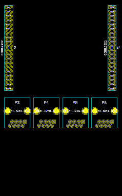
- QLCgpio3.png (3.91 KiB) Viewed 3809 times
The PCB would be 2mm thick and the cables could be secured with tie wraps. That is why the board is so long (and thick).
Once I get a little further you get the zip file with the project and the libraries. We could review and refine the design for a while.
The middle area on the board is for optic isolators and the dc-dc isolated power supply.
PS. silly me, the RJ45 connectors have to flip 180 degrees in order to get the cables going south and not north.
Re: Use GPIO pins to trigger scenes
Posted: Thu Jun 11, 2015 12:22 pm
by karrika
Here is a first try on the schematics. There is just 12 input pins available. The rest are needed elsewhere. Comments?
Re: Use GPIO pins to trigger scenes
Posted: Sun Jun 14, 2015 8:13 am
by iamchrislaurie
That's look cool!
I have been looking at another approach, using the GPIO pins directly via a 16 channel multiplexer like this one
http://www.ti.com/product/cd74hc4067
In this case you would have many of them, all using the same 4 address pins simultaneously (an address bus) then you would need 1 pin per chip to read the values back. A 12 pin arrangement would allow 8 of these giving you 128 buttons/sliders - sliders would need some form of ADC.
This then avoids using the SPI bus altogether.
Thoughts about this? I am currently playing with this in a with a teensy 3.1 board (handles analog) and then create either a HID or MIDI device.
I guess I'm mentioning it here because I hope that whatever plug-in software is written, it would also make it possible to use this approach.
Re: Use GPIO pins to trigger scenes
Posted: Mon Jun 15, 2015 6:22 am
by karrika
Using latches instead of SPI is technically ok.
But the
http://elinux.org/RPi_Low-level_peripherals describes what kind of support for GPIO is in the kernel. This text also mentions the Arduino style of accessing pins over I2C and SPI networks.
In the schematics I posted you may notice the texts WiringPi XX. These numbers are the Arduino-style pins recognized automatically by the wiringPi libraries. There is also C-libraries that support pin numbering directly over SPI devices.
The benefit with SPI or I2C chips is that they support internal pullups, mode change to inputs or outputs and interrupts.
The multiplexing approach requires constant polling of the data which is not currently in the mainstream of Raspberry Pi. So I am afraid that there would be poor software support and we would have to maintain more code if we take the latch approach. And I am a bit lazy...
But if someone has started to support libraries using latch techniques I have nothing against this approach either.
Here is a small snippet of the SPI approach. This is a very straight forward way to deal with extended I/O. And there is very little code to maintain. I could have used the individual I/O pin approach here that might have been easier to read. But now I decided to write the code using byte reads for faster speed. So there exists also a pin-by-pin API. As well as python APIs if you don't like C.
Python is a good choice for sending OSC messages to QLC+ as there is a generic OSC library available.
Code: Select all
void spiSetup (int speed)
{
  if ((myFd = wiringPiSPISetup (SPI_CHAN, speed)) < 0)
  {
    fprintf (stderr, "Can't open the SPI bus: %s\n", strerror (errno)) ;
    exit (EXIT_FAILURE) ;
  }
}

// Write a byte to the SPI I/O pins
void writereg(int chip, int reg, unsigned char data)
{
  unsigned char buf[3];
  int status;
  int i;
  buf[0] = (0x40 | (chip << 1)) & 0xff;
  buf[1] = reg & 0xff;
  buf[2] = data;
  status = wiringPiSPIDataRW(0, buf, 3);
}

// Read a byte from the SPI I/O pins
unsigned char readreg(int chip, int reg)
{
  unsigned char buf[3];
  int status;
  buf[0] = (0x41 | (chip << 1)) & 0xff;
  buf[1] = reg & 0xff;
  buf[2] = 0;
  status = wiringPiSPIDataRW(0, buf, 3);
  return buf[2];
}

void setDataInputs()
{
  writereg(0, 0, 0xff); // IODIRA all bits as inputs
  writereg(0, 6, 0xff); // IODIRA set pullups active
}
Re: Use GPIO pins to trigger scenes
Posted: Mon Jun 15, 2015 11:29 am
by boxy
Hi Karrika,
Could I recommend 10nF 50V capacitors to ground on the switch inputs and small diodes across the opto LEDs? This would make the circuit bomb proof in terms of ESD and connection to the mains etc. Diodes could be BAS16s or BAV99s (surface mount) or 1N4001s (through hole but a lot bigger).
Re: Use GPIO pins to trigger scenes
Posted: Mon Jun 15, 2015 5:56 pm
by karrika
Hi boxy,
Thanks for the reminder. I added surface mount caps and diodes.
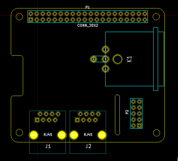
Here is the layout so far. This is still not completed but gives an rough idea. The size of the board is 50mm x 100mm.
The 4 holes on the top part are for securing the pcb to the chassis.
The 6 holes at the bottom is for securing the Ethernet cables with some plastic tie wraps. The pcb will be very thick (2mm) to support the cable ties.
The flat cable coming in from the Raspberry Pi 2 may come directly from the RPi or from some other future module like DMX. The cable to the right goes to the next board in this series.
If you have improvements or concerns about the mechanics please add a comment.
Re: Use GPIO pins to trigger scenes
Posted: Sat Sep 05, 2015 7:09 pm
by mcallegari
Hey guys, I have implemented a GPIO plugin for QLC+.
Would you be willing to help testing it ?
Basically it's meant to run on the Raspberry Pi.
Re: Use GPIO pins to trigger scenes
Posted: Sat Sep 05, 2015 7:09 pm
by stef35
Hello
I would be pleased to help the project by testing this plugin?
Just tell me how i can help
mcallegari wrote:Hey guys, I have implemented a GPIO plugin for QLC+.
Would you be willing to help testing it ?
Basically it's meant to run on the Raspberry Pi.
Re: Use GPIO pins to trigger scenes
Posted: Sat Sep 05, 2015 7:09 pm
by enterius
Hi Massimo.
I would like to help with testing GPIO plugin as I'm very interested in using it in my applications. Unfortunately I can't find any documentation for this plugin and I'm kind of lost about how to use it. So please feel free to write to me with some instructions and i will do all the needed testing.
I already soldered some micro-switches and LEDs to GPIO connector, but I have no idea how to bind them to any buttons and functions in QLC+.
Best regards
Krzysztof
mcallegari wrote:Hey guys, I have implemented a GPIO plugin for QLC+.
Would you be willing to help testing it ?
Basically it's meant to run on the Raspberry Pi.
Re: Use GPIO pins to trigger scenes
Posted: Mon Sep 07, 2015 2:35 am
by mumbles
This sounds like an interesting project!
Do you think it's possible to get this circuit to fit on a 65x56mm pcb to meet the official HAT requirements?
This would make it easier to adapt CAD files to print cases. And in most cases itd fit existing Pi cases.
https://www.raspberrypi.org/blog/introd ... y-pi-hats/
My daily job as a customer system integrator and my dealings with RJ45 connections for a big majority of equipment has taught me, the zip ties could actually cause 2 flaws 1) RJ45 jacks to be pulled off the PCB due to the ziptie pulling down on RJ45 plug causing the back of the jack to pull up on solder joints. This tension combined with even a little ambient vibration will eventually cause failure to the pins inside the RJ45, solder connections of RJ45. 2) makes it difficult to release lock/ set on RJ45 plug.
There is an industry standard that states cables should not be fastened any closer than 6 inches to termination. This is to prevent the above issues.
Re: Use GPIO pins to trigger scenes
Posted: Sun Oct 11, 2015 11:11 am
by karrika
The HAT idea sounds good. Very good actually. I would love to fit isolated DMX out and as many isolated GPIO pins as possible. Thanks for a great idea.
Combined with the new 7" LCD this would be a very nice unit. A 10" cabinet with clamped cables coming out of one end. I love it!
- QLC+HAT2.png (10.05 KiB) Viewed 3056 times
The big connector would be DMX out, the small one an extension for expanding through serial bus. At the bottom two sockets for 8 input switches.
Drawing the circuits tonight
--
Karri
Re: Use GPIO pins to trigger scenes
Posted: Sat Oct 17, 2015 6:16 am
by karrika
Here is the layout and wires of the brand new DiscoHAT.
It has an isolated DMX output and 8 isolated input switches. The edge connector has ws2801 bits.
I would like to have QLCplus and HAT in the name of the board. But on the other side it becomes too long. Perhaps DiscoHAT would be good?
There is also an eeprom for the linux driver that populates the used bits at boot time into the Device tree as the HAT specs require.
I sent in an order of 10 pcb's earlier today. Within a few weeks I should have the protos ready. The price is "cheap". Less than 50€, more than 10€. The idea is to have a single 100 boards production run that should cover the need of DiscoHAT's for all eternity

Re: Use GPIO pins to trigger scenes
Posted: Sat Oct 17, 2015 6:16 am
by mcallegari
karrika wrote:Here is the layout and wires of the brand new DiscoHAT.
Looks awesome Karri !
In the end will it have a "passthrough" strip to pack another hat over it ?
Is it for RPi 40 PIN IO only or will it be possible to plug it also on older RPi 1 ?
From the mechanical point of view, do you have screw holes in the same positions of the RPi ones ? Otherwise a floating board can easily get broken and can damage the RPi too.
Will you send one to me ?
How about calling it QLC+HAT ?
I'm actually kidding, since you are designing a generic board, not specific to QLC+
Last thing: have you seen
this post ? Basically I need to understand if the Eurolite adapter works or not on OSX.